A quick overview of the MVNA-8-350
millimeter vector network analyzer produced by AB Millimetre
The Vector Network Analyzer MVNA-8-350, which is produced by AB
MILLIMETRE since 1990, is the only all-solid-state electronics
millimeter and submillimeter waves spectrometer/network analyzer, which
allows to do vector measurements (simultaneous measurements of both,
the amplitude and the phase of transmitted/reflected signal) over very
broad frequency range extending from 8 to 1000 GHz (wavelengths from 4
cm to 0.3 mm). It is the state-of-the-art millimeter and submillimeter
domain diagnostics and spectroscopy tool, for many applications, from
space telecommunications and satellites diagnostics, to physics and
chemistry spectroscopy.
Over 60 MVNA's are in use in civilian sector at present.
A symbolic map shows worldwide distribution of our MVNAs.
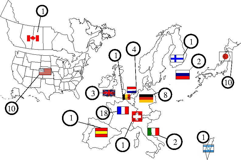
The numbers in circles show how many AB Millimetre Vector Network
Analyzers MVNA 8-350 have been sold in each country since 1990.
Our MVNA is based on an original, patented, design (CNRS France 1989,
US Patent Goy-Gross 1992). According to this configuration, experiments
are possible even without directional couplers. This explains the fact
that millimeter heads are small and light.
Except for the lowest frequency band, from 8 to 18 GHz which works with
coaxial cables, all higher frequency
bands use such small waveguide millimeter heads.
 ( click at the picture to see it in full size )
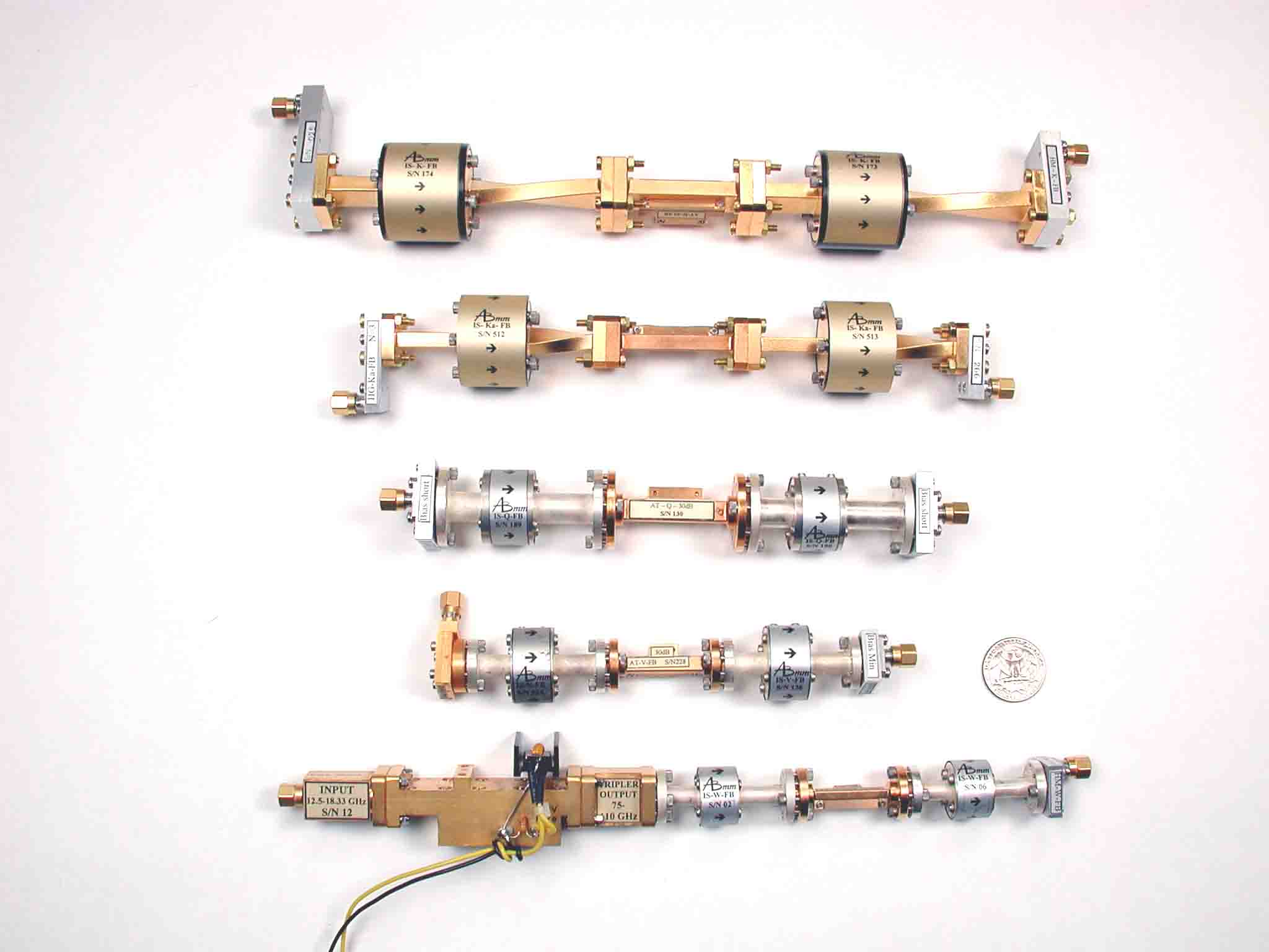
The above figure shows millimeter heads for standard microwave
bands from 18 to 110 GHz.
Our unique design explains also the extremely high frequency
capability, where directional couplers don't exist. A single pair of
extensions, see following two pictures, permits the continuous
frequency coverage from 140 to 1000 GHz.
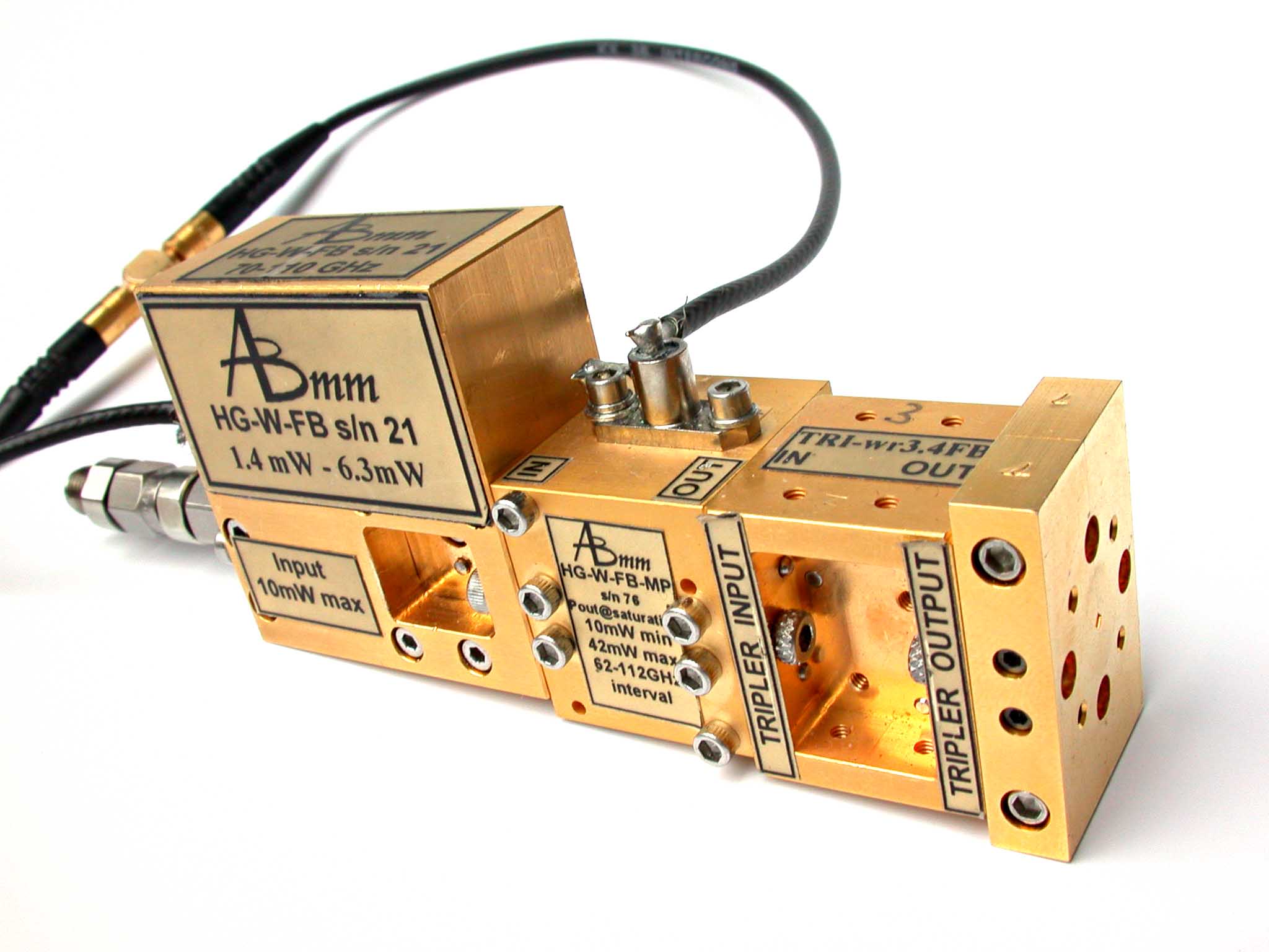
Source and Detector Solutions for the
Millimeter Vector Network Analyzer MVNA-8-350
The device shown above provide Full Band coverage source for:
- 660-1000 GHz frequency band in configuration like that shown in
the above picture with WR-1.2 waveguide output
- 220-336 GHz frequency band upon removing the vertical block at
the right side of the source
- 62-112 GHz frequency band after removing the tripler block, then
with WR-10 waveguide output
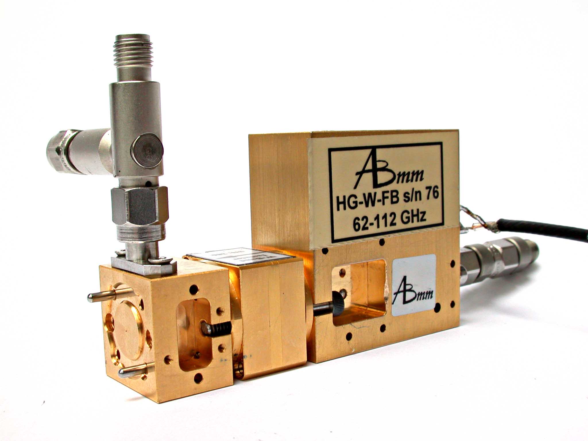
The detector set-up as shown above provides:
- Full Band coverage for 660-1000 GHz spectral range
- WR-1.2 waveguide input coupling
- Ca 80 dB dynamic range
Extensions for the Millimeter
Vector Network Analyzer MVNA-8-350
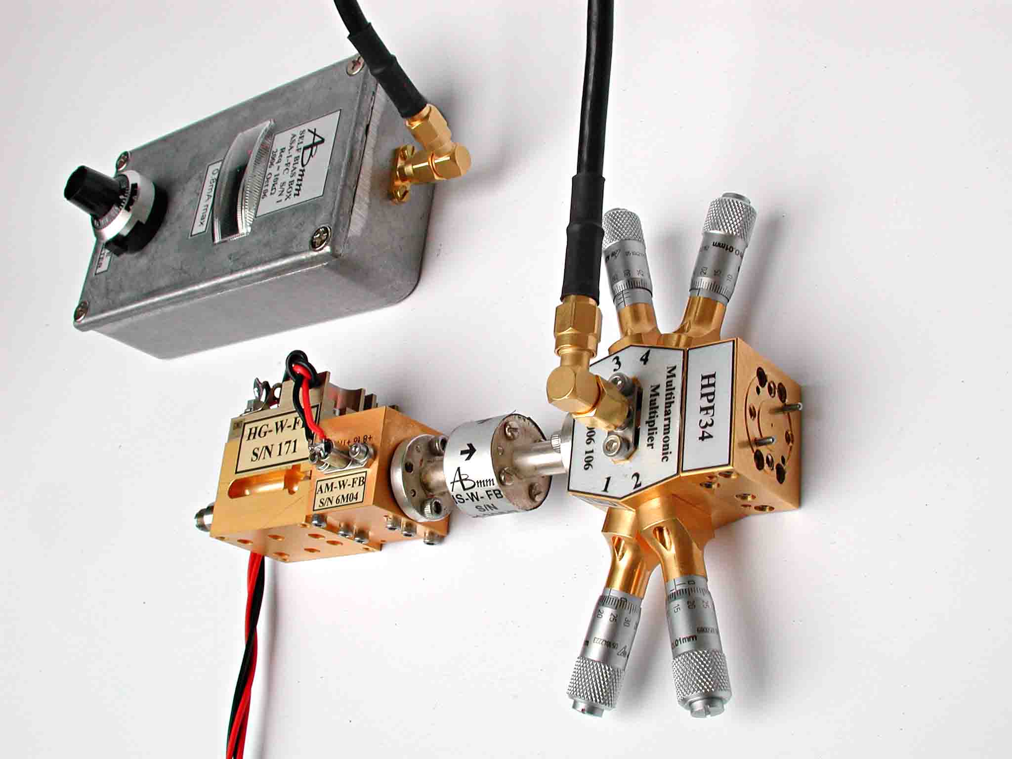
The figure above shows ASA-1-FC extension (Automatic Source Association
Number 1- source side -
Full frequency Coverage). The six times multiplier is fed from the MVNA
with the centimeter range wavelength
microwaves through an SMA coaxial connector (on the left), providing
millimeter waves
output signal in the frequency range of 62-112 GHz. That signal is
subsequently amplified and sent, through a Faraday isolator, to the
tunable harmonic multiplier, TMU. The choice of the driving signal
frequency,
of the multiplication factor (between 2 and 10), and of the attached
high-pass filter HPF, provides
the full frequency coverage in the range between 140 and 1000 GHz.
Electronically controlled frequency sweeps with a minimum span of 9 GHz
are possible in the whole range.
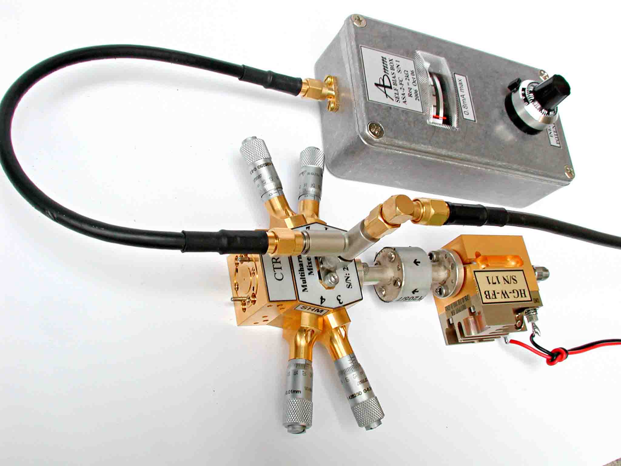
ASA-2-FC extension (Automatic Source Association Number 2 - detection
side - Full Frequency Coverage).
This setup is rather similar to the ASA-1-FC source (previous picture).
It does not include millimeter wave amplifier, and the tunable
detection device SHM is a Schottky Harmonic Mixer. The bias tee on the
top of SHM provides a separation of the DC bias current from the IF
detected beat signal.
ASA-2-FC is used to detect signals generated by ASA-1-FC in the
frequency range from 250 GHz (the cutoff frequency of the input
waveguide) up to 1000 GHz.
System Capabilities
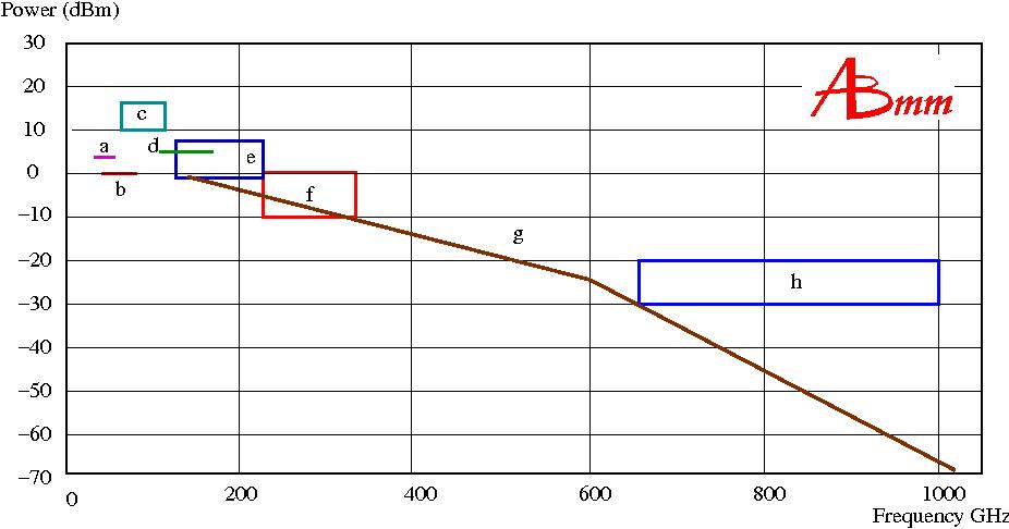
Such a broad selection of available sources allows us to cover the whole spectral range from 8 GHz to 1 THz.
The diagram below shows the list of available MVNA sources above 29 GHz, together with their frequency range and typical
output power. For details see our product description Picture 16.
 ( click at the picture to see it in full size )
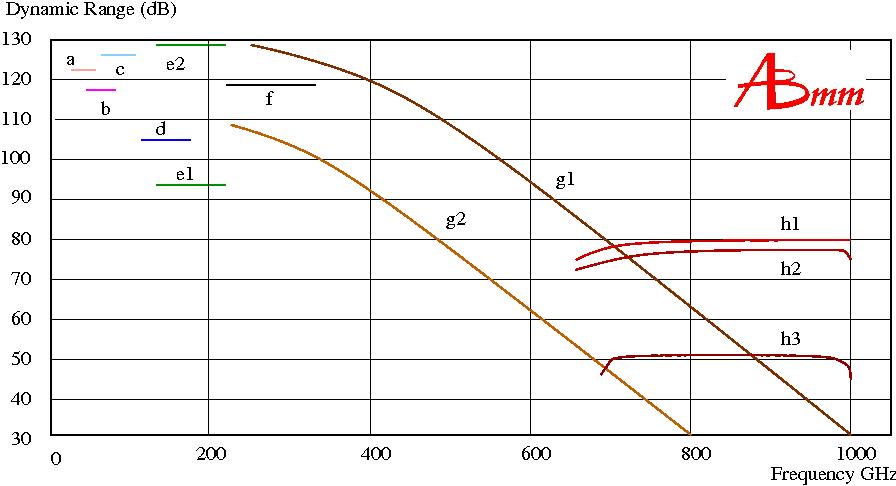
Those sources, combined with our choice of detectors provide very broad dynamic range of MVNA,
a figure of merit which is usually more significant that the source power itself. Large DR
is particulary important for experimental set-ups or DUT introducing considerable losses into
the radiation path. In such situations MVNA, due to large dynamic range offers comfortable
and meaningful S/N ratio making data collection faster and more reliable. In the diagram below
we plotted the DR for several typical source-detector (described in detail in our
Products description section) combinations.
 ( click at the picture to see it in full size )
The observed dynamic range decreases with frequency, as shown in the
picture above. For details please see our Products description Picture 16.
The standard VNAs are dedicated to the 4S-parameter measurements. On
the contrary, most applications of AB MILLIMETRE's MVNA are with a
single detection at a time (1S), model MVNA-8-350-1, or with
simultaneous transmission-reflection (2S), model MVNA-8-350-2. The
full-reverse 4S-parameter configuration (model MVNA-8-350-4) is very
rarely needed. On the other hand, an original configuration of the
MVNA, model MVNA-8-350-1-2 (and also models -2 and -4), makes possible
to work, with a single source and a single detector, at two frequencies
simultaneously, like 51 GHz and 68 GHz, or 500 GHz and 600 GHz, etc.
The MVNA is used at present in several research laboratories, and at
universities. Two main kinds of application of MVNA can be
distinguished: engineering studies of millimeter
waves devices, and millimeter-submillimeter spectroscopy.
The first group of applications is prevalent at Electrical Engineering
departments, developing
microwave and infrared techniques. Faster electronics circuits and
faster transmission lines require higher bandwidth, hence need to
develop and optimize faster active and passive electronics,
electrooptical devices, and diagnostic tools. MVNA is the best possible
tool for testing of millimeter wave antennae, for network analysis
of broad-band high frequency components, and for materials characterization.
That type of applications is
also common at physics departments, where millimeter wave
instrumentation
is used as a detector, like in radioastronomy, as a diagnostic tool, or
as a powerful heating source
for instance in plasma fusion physics.
Example Applications of MVNA
 ( click at the picture to see it in full size )
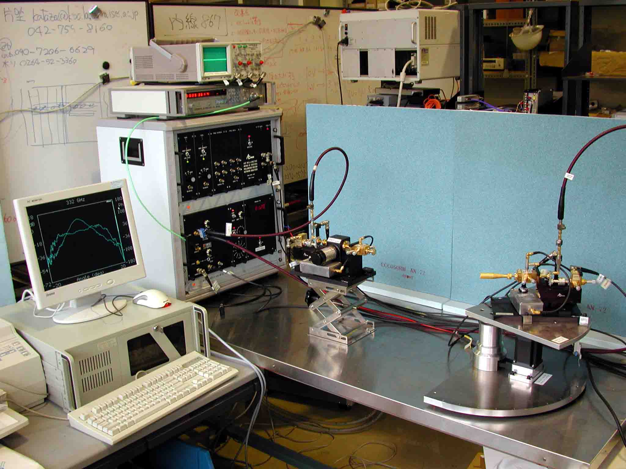
The picture above shows measurement of a 332 GHz antenna at National
Astronomical Observatory of Japan. The MVNA is the model MVNA-8-350-1-2
allowing dual-frequency technique. It is linked to the extensions by
flexible coax cables. On the PC-Monitor appears the Gaussian antenna
diagram, with a parabola for amplitude (in dB), and a flat line for
phase. The delivered extensions, plus the delivered ordinary millimeter
heads, can cover the 29-1000 GHz interval.
The extensions shown in this picture, are of the former type, called
ESA (Extended Source Association). They were built with mechanically
tunable W-band Gunn sources as local oscillators. In the picture one
can see ESA-1-A-FC on the left (with a rotary vane attenuator
controlling the intensity of emitted power), and ESA-2-FC on the right
(with the horn antenna under test). Due to mechanical tuning
requirement that setup had very limited possibilities of electronically
driven sweeps, contrary to the new ASA extensions.
(Picture: courtesy of Professor Yutaro SEKIMOTO, National Astronomical
Observatory of Japan, Alma-J Group.)
 ( click at the picture to see it in full size )
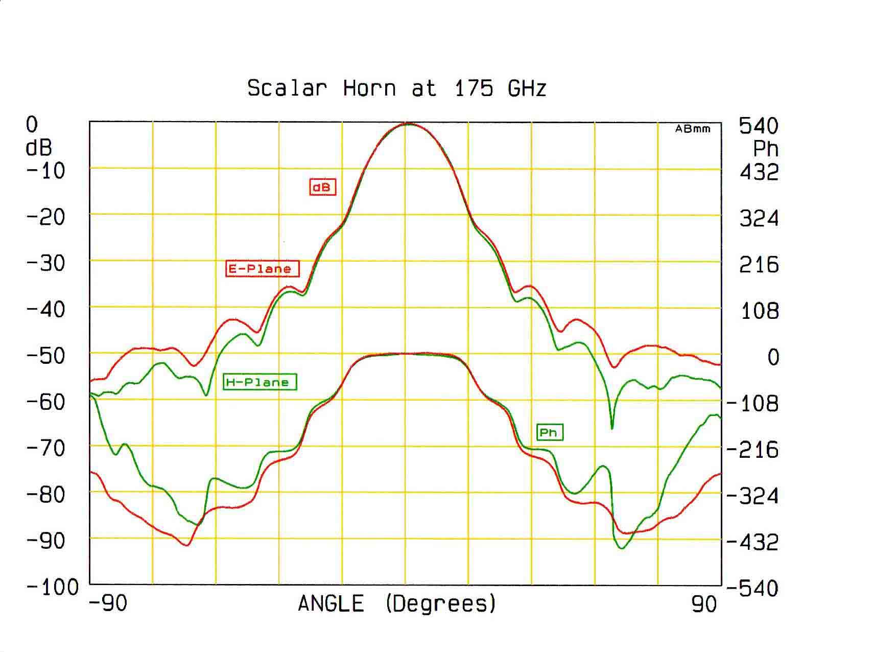
In the above plot the measurements of an angular antenna diagram of a
scalar (corrugated) horn are shown for the frequency of 175 GHz. The
antenna under test, attached to the detection unit, is rotated over the
range
from -90 ° to + 90 ° from the optical axis of the source, which
is located in the "far field" conditions.
The amplitude scale of the signal is shown in dB on the left side of
the plot. The phase scale, in degrees,
is shown on the right. Green curves correspond to the rotation plane
parallel to the electric field vector E of the millimeter wave. Red
curves correspond to the rotation plane
perpendicular to the electric field vector E of the millimeter wave.
Please note that the phase data are shown,
for clarity, upside-down. The above diagram demonstrates that the
antenna has almost perfectly symmetrical Gaussian beam characteristic
around the optical axis and very small
side lobes. The phase response is flat (due to locally plane wave) and
the amplitude angular dependence is parabolic for small angles on the
logarithmic (dB) scale. Such response is expected for the Gaussian beam
since the intensity of the radiation I decreases with the
distance from the optical axis a like I ~
exp(-a*a) .
 ( click at the picture to see it in full size )
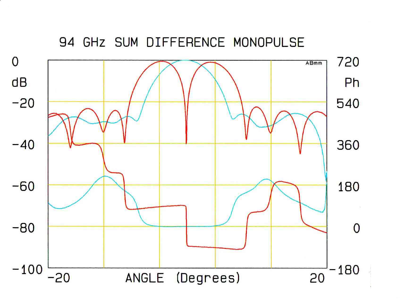
The picture above shows printout of diagnostic measurement of a
"monopulse" antenna, used for guidance systems, obtained at 94 GHz
during a 20 sec. angular sweep. The amplitude is shown in the upper and
the phase in the lower part of the figure. Two pairs of waveguides from
the antenna are combined in order to obtain both, the sum (shown in
blue) and the difference (shown in red) signals. The "sum" response
corresponds to the ordinary angular antenna diagram for a Gaussian
beam, as shown in the previous picture,
with a parabolic shape of the amplitude and a flat phase response close
to the axis of symmetry. The "difference" signal displays a sharp local
minimum of the amplitude and a step-like response of the phase.
Such a characteristic is useful for guidance applications where the
feedback system attempts to
keep the antenna oriented at the maximum of the "sum" signal, and uses
the sign of the "difference" signal
phase for the track correction.
 ( click at the picture to see it in full size )
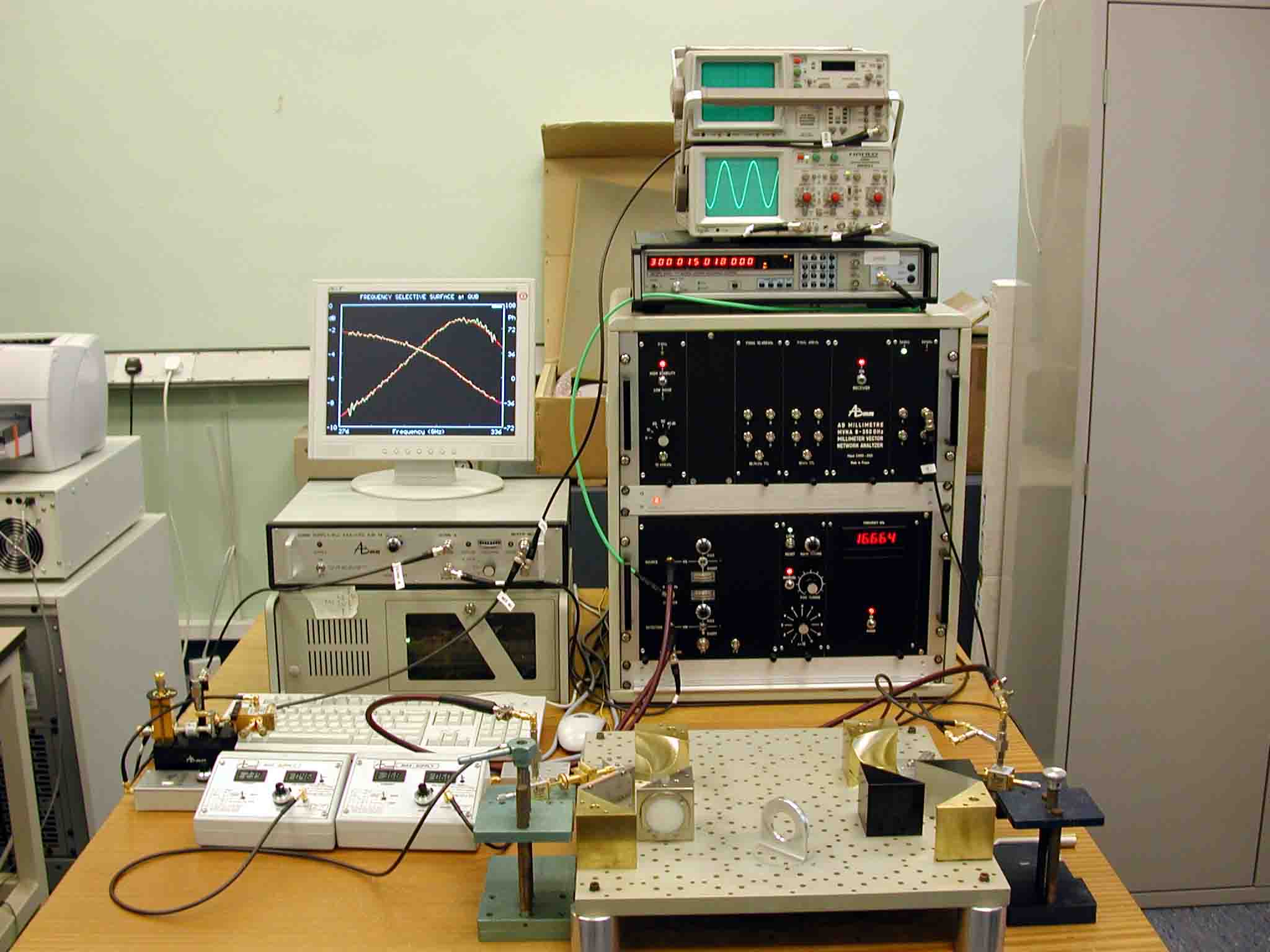
At the Queen's University in Belfast, Northern Ireland, frequency
selective surface mirrors (FSS) are tested between 100 and 550 GHz in
the Electrical Engineering Department. The FSS mirror, positioned with
the surface at the angle of 45 degrees to the beam direction in the
microwave beam, is designed to transmit with a small loss at a given
frequency, near 300 GHz. The MVNA itself, with its control oscilloscope
and frequency counter-stabilizer, is driven by a PC computer. The
control oscilloscope shows the detected millimeter wave
amplitude, phase and signal-to-noise ratio.The picture on the monitor
shows the transmission of the FSS between
274 GHz and 336 GHz.
(Picture: courtesy of Professor Robert Cahill, Queen's University, The
Institute of Electronics, Communications and Information Technology,
Belfast.)
 ( click at the picture to see it in full size )
The photo above shows microwave antennae, used for coupling of the
free-space propagating radiation to the waveguide in the range between
100 - 600 GHz. Such antennae are small and efficient. Each of the four
pairs of scalar (corrugated) horns, provides a very clean Gaussian beam
over wide frequency range. The emitted Gaussian beam can be refocused
in a Quasi-Optical bench with 4 elliptical mirrors, see the previous
and the next pictures.
A new 5-mirror 44-1000 GHz QO bench allows simultaneous transmission
and reflection measurements without using of directional couplers,
thanks to polarizing grids.
 ( click at the picture to see it in full size )
In the system shown in the photo above, a quasi-optical bench is used
for transmission (T) - reflection (R) characterization of dielectrics
in the range 44 GHz - 260 GHz at the Electrical Engineering department,
Signal Theory and Communication, Microwave and Millimeter Waves Group
of Universidad Publica de Navarra in Pamplona, Spain. (Picture:
courtesy of professor Mario Sorolla, UPN, Pamplona).
 ( click at the picture to see it in full size )
The above picture shows MVNA-measured data of high-loss material. The
amplitude, in logarithmic scale, of transmitted signal (left scale),
and the phase (right scale) vary almost linearly with the frequency.
 ( click at the picture to see it in full size )
Transmission T and reflection R versus frequency of a plane-parallel
2.79 mm thick slab of low-loss material. It shows characteristic
Fabry-Perot resonator-like oscillations of signal amplitude (left
diagram). T has a maximum where R has a minimum, and vice-versa. The
software fitting of T (thick lines) gives precise values of the
permittivity e'=3.17, and the loss tangent=0.007
in the whole spectral range, 40 GHz - 170 GHz.
 ( click at the picture to see it in full size )
The amplitude of transmitted T (thick line) and reflected R (thin line)
signal is shown for measurements of the 2.56 mm thick ferrite slab (not
magnetized) between 40 and 170 GHz.
There is a very strong absorption band observed between 55 GHz and 73
GHz.
 ( click at the picture to see it in full size )
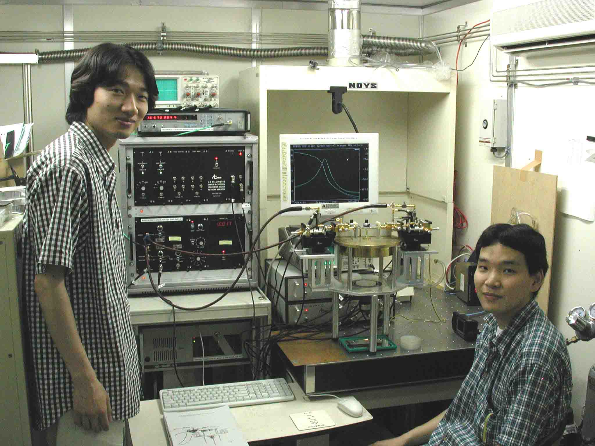
A precise measurement of dielectric losses in very low-loss materials,
including gases, can be made by perturbative technique in an open
cavity,
shown in the middle of the picture. The resonance of empty cavity with
the Q-factor reaching 180 000 was measured at 700 GHz
at the Nippon Institute of Technology in Saitama, Japan with the set-up
shown in the above photo.
The observed resonance shape can be seen at the monitor in the picture.
(Picture: courtesy professor Yasuo Watanabe, Nippon Institute of
Technology, Japan.)
 ( click at the picture to see it in full size )
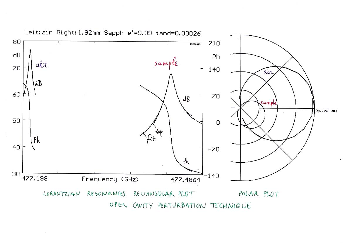
Introducing a sample (a 1.92 mm thick sapphire slab) into the cavity
shown at the previous picture shifts resonance frequency and damps the
resonance. From these changes of frequency and cavity Q-factor
dielectrics parameters of the sample
can be calculated. The diagram above shows traces of the resonance of
empty cavity, and of the cavity with the sample. Signal amplitude scale
in dB is shown on the left, and the phase in degrees on the right.
From
measured changes of the resonance shape and position (shown in polar
coordinates in the right part of the picture) one
can calculate dielectric parameters of the sample.
The second group of applications of MVNA is commonly related to
research in Science Departments. That research includes radioastronomy
and plasma fusion as mentioned above, but also spectroscopy of
molecules and atoms, studies of elementary excitations in condensed
matter,
physics of metals and magnetic materials, and studies of magnetic
resonances. In particular, in several leading high magnetic field
laboratories worldwide, MVNA is intensively used for electron
paramagnetic resonance, and cyclotron resonance studies .
 ( click at the picture to see it in full size )
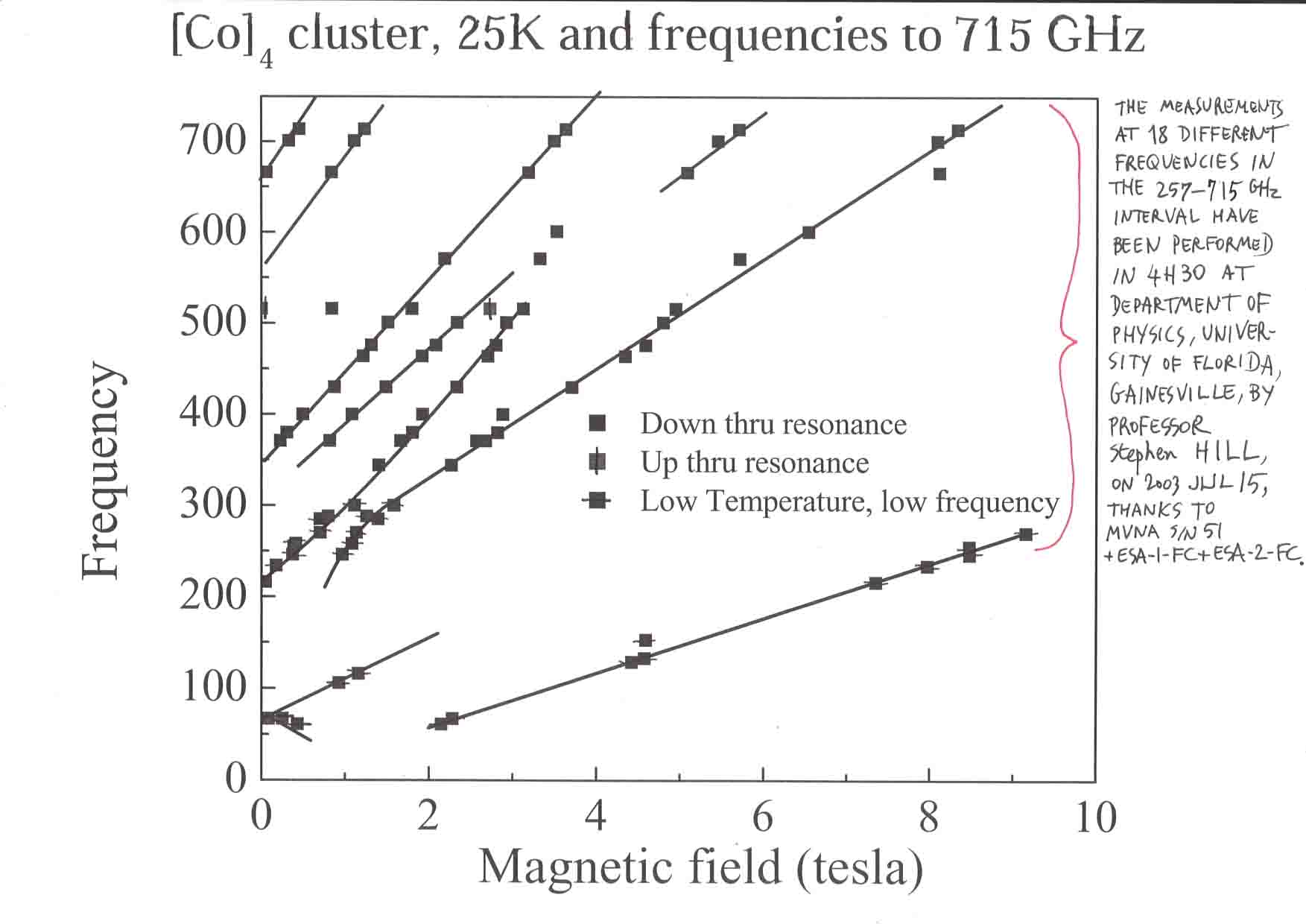
An unique feature of MVNA - very broad frequency coverage allows for
rapid measurements
of magnetic resonances at several different frequencies corresponding
to a broad range of magnetic fields. For example, at the National High
Magnetic Field Laboratory, in Tallahassee, FL, USA., there are already four
MVNAs which are used for a broad scope of experiments, and in
particular for variable frequency magnetic resonance studies.
Thanks to the dual-frequency
technique it is possible to scan at 18 different frequencies (each
point in the picture corresponds to one magnetic field sweep which
takes approx. 15 minutes) in the 257-715 GHz interval with one of the
MVNA's, in less than four and half hours.
J. Liu, S. Datta, E.
Bolin, J. Lawrence, C.C. Beedle, E-C Yang, P. Goy, D.N. Hendrickson and
S. Hill, Anisotropic exchange in a tetranuclear CoII
complex, Polyhedron 28, 1922-1926 (2009).
[Home| Company| Products|
Applications| How
to reach us| Downloads| Links|
Write to us
Please send your questions, inquiries and
comments to the following address:
abmillimetre@wanadoo.fr
AB Millimetre
52 rue Lhomond
75005 Paris, France
tel.: + 33 1 4707 71 00
fax: + 33 1 4707 70 71
Copyright © 2013 AB Millimetre, All Rights
Reserved.